Out For a Stroll

Previously I’ve shown attaching the legs to the body, but I haven’t done much with the feet – that’s because it felt fairly shallow to show the motors getting attached without showing it actually driving. To get it to the point of driving, however, took a lot of tweaking and electrical work. However, it has finally all come together, and K4 took his first steps! The shortened version of it is: this was a pain, many parts took a lot of tweaking and work to stabilize properly, but here are his first real steps:

This was a long time in the making, however, so this will be a fairly long post describing what it took. For reference, here are the scooter motor feet after the last update:

So, what needed to happen, was holes had to be drilled at the top for the ankle to mount to the foot, three holes had to be drilled in each side for the motor mounting screws, and then a much larger hole between those for the motor sprocket to fit into (a sprocket is a gear, but instead of touching a gear, it touches a chain), and then finally holes had to be drilled for the wheel axle to fit into. Let me summarize something like 40 hours of work by simply saying that getting all of those into alignment was difficult. Very difficult. Since I had to drill all the holes by hand, and the feet are such odd shapes, I ended up having to use a lot of washers and various spacer rings cut from scrap plastic to get things together. However, with a lot of help from my dad holding, cutting, and generally pointing out where I was making mistakes I did finally get it all in place.

What you can’t see here easily is that the chain is actually much too long for the feet. I had to special order master links for the chain and then use a dremel grinder to split it, and remove 3-4 links. I don’t know the exact number because I actually had to go through the process of removing links twice, because out of an abundance of caution the first time I shortened the chain, I didn’t shorten it enough. It was an extra pain in the ass, but at the end of the day I was able to get a pretty solid connection between the sprockets so even though it was time consuming, I can’t complain too much about it. One distinct issue that I will have to be conscious of going forward is that due to how sensitive the alignment of these parts are, I am hesitant to build the foot normally. I would rather have magnets, velcro, or perhaps some sort of latching system in place that would grant me quick access to the motor screws and the axle to ensure that if it comes out of alignment, I can quickly shift it back.

This overhead shot of the feet shows where the axle and motor are mounted and gives a bit more indication of how things can get out of alignment. It’s hard to tell because of where the motor power cable is in the above image, but I actually believe that the bottom foot has its wheel out of alignment. What I actually had to do to compensate for this was drill a slot for the axle to sit in, and then move it. I tried using lock washers and regular washers to hold it in place, but every time I powered the motor I found it slipping back into its old position. To resolve the issue I actually took some scrap plastic and back-filled the slot to prevent the axle from being able to move. So far this solution has worked well enough to be passable, but as mentioned previously I’m worried enough that I’m leaving adding the sides to the feet until just about the very last steps, lest anything else I do cause them to have problems that I need to correct.

I will save the electronics necessary to get K4 moving for its own, separate post, in the interest of trying to keep things organized.

This’ll Make Your Head Spin

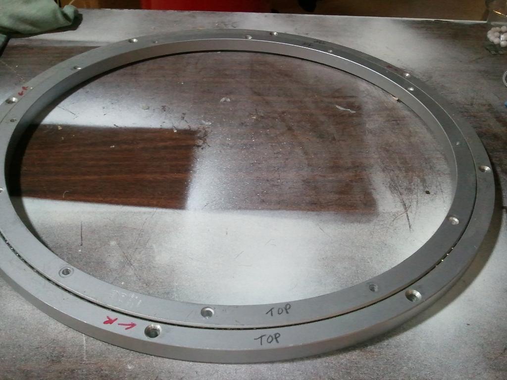
This entry is going to go into detail on how I got K4’s dome to spin. The secret ingriedient here is a Lazy Susan Rockler bearing. This bearing allows you to mount something to one of two concentric rings, which will then spin inside of the other ring. In this way I can attach the bearing to the body of K4 and then have bolts stick up which will attach to the dome and allow it to spin. Here is a picture of the bearing:

This isn’t my bearing – I forgot to take a picture of it before I mounted mine.

In order to make the ring work, what you actually have to do is drill out the holes on the inner ring. Normally those holes are just for some rubber feet which are used to hold up whatever platter you’d put on it. In our case, since we need to put bolts all the way through them. This is a pretty simple task, though – the ring is made of aluminum and is mostly drilled already. Then it’s simply a matter of placing the bearing on top of the body, marking the holes and drilling them out, and finally putting the bolts through the holes. Below is the bearing attached to the body, with some small pieces of wooden being used temporarily as spacers.

You can see the bearing mounted to K4 here

With these bolts sticking up out of the bearing you can see how the ring the dome will be attached. In order to make sure I got the bolts lined up with the holes I would then drill out of the dome, I applied a little bit of nail polish to the bolts and then placed the dome on top of it. The pieces that attach to the dome are actually two parts: a sort of a skirt piece, which comes down and hides the rockler bearing, and then the dome itself. In this next picture you can see the skirt piece placed atop it. When I got the skirt it was one solid circle of plastic which needed to be cut out – which was significantly more of a pain than you might think, seeing as I can’t get it under a band saw or anything like that, I was forced to use the dremel.

Rockler bearing with “skirt” on it

The final step to get the dome on was to cut a circle out of plastic which the dome would be glued to. Since the dome I bought didn’t have any pieces inside of it to give it rigidity or to allow mounting, it was necessary for me to cut one. To do this I cut a circle slightly larger than the inside diameter of the dome and then used the dremel to slowly bring it down to the right size. This was simple, but extremely slow and tedious process. There are many different shapes people use for the dome cutout, but in my case I opted for the simplest in a simply bar across – but frequently people make a peace sign shape or even a three pronged sort of fork shape instead.

Dome with the mounting and crossbar piece attached

Once this piece was on, the dome could simply be placed atop K4 and spun!

A Light at the End of the Tunnel

So, having gotten much of the body painted a big next step is getting the lights in place!

I ordered a pre-soldered light kit with a small circuit board with some code to set the LEDs to blink and change color at seemingly random intervals. What this allows me to do is worry simply about mounting the lights rasther than needing to buy a circuit board, program it to light LEDs, and solder each LED individually onto the board. These tasks are all trivial, but fairly time consuming. As such, I didn’t see it as necessary to do myself – especially since as an amateur at soldering I felt like somewhere in the 200 or so lights I’d inevitably make a very frustrating mistake. In the below pictures you can see the holes where LEDs/detail would go and how I had to dremel/sand it down to get the edges flush, as well as a picture of the assembled lights.

Dome where unaligned cuts are visible

Mounting the lights was a relatively simple process, all I had to do was wire them all together to the main circuit board by daisy chaining them, cut the appropriate slots into the dome, and glue them in place. Additionally, each set of lights comes with a small filter, for lack of a better word, that makes it look like a light panel, as opposed to a bunch of individual LEDs. The effect is actually pretty impressive – the video below illustrates the effect.

This shows the LED lights and how they look through the filter

It was very satisfying to get the LEDs in place! With lights working, K4-G8 really feels like he’s starting to come to life!